Cutting-Edge Engineering For Efficient Production Testing
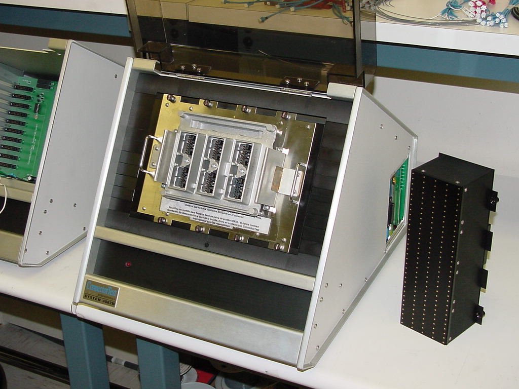
ConnectorTest International's test systems offer significant manufacturing and product marketing advantages, some of which are outlined on this page. High-quality OEM manufactured test modules fit into the rugged aluminum chassis using quarter-turn aircraft fasteners, allowing testing of several devices at a time, yielding more efficient testing and much greater product throughputs in the production environment.

System Features:
- Rugged aluminum encased tester; mid-tower computer w/ 3.4 GHz Intel Core i-3-3240 processor; 4 GB RAM; 1 TB HDD; 19" LCD Monitor and HP Laser Printer. Includes Microsoft's Windows 10 Professional OS and ConnectorTest International's system software.
- Compact workstation. Installs in minutes; easily portable to other test sites. All tests were performed by a single operator with elementary computer skills. Tester itself consumes less than 40 watts of power!
- Password protected 'Supervisor' menus for programming part numbers. 'PIN' codes for up to 20 'Operators.' Abbreviated 'Operator' menus allow only basic testing and printing functions to be performed.
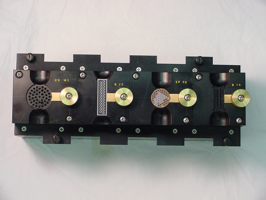
- Modular test bed w/ 320 points for connector testing and 160 points available for Cable Continuity testing. Test multiple parts/different parts in same test cycle. Cumbersome test cables/harnesses no longer needed for using this advanced test system.
- No more shuffling connectors/cables from one test station to another to perform various QA tests. All selected tests are conducted concurrently on CTIs advanced test systems in a fraction of time compared to slower, outdated, commercially available ATE systems.
- Low-cost test modules/fixtures for connector/cable assembly devices, sub-assembly devices and capacitor array, or ConnectorTest may adapt to your existing fixtures/test modules.
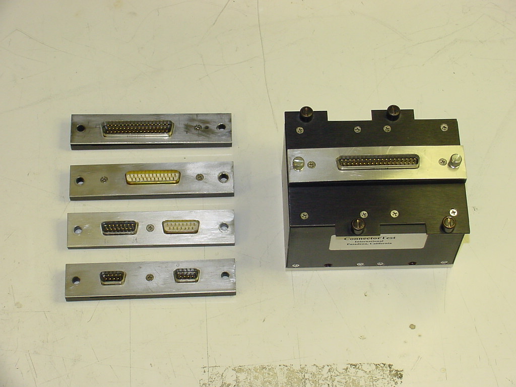
- Unique, efficient fixture designs – A single CTI test fixture handles the entire 'D' sub and micro 'D' connector lines. This equals efficiency, versatility, cost-effectiveness.
- High-speed testing of each pin for ALL programmed tests in one test cycle!
- Pin selectable test voltages, dwell times and capacitance ranges, Zener voltages (Uni-polar, Bi-Polar); up to 10 separate individual groups of ranges – individually selectable.
- Checkbox for selecting 'Minimum IR Dwell Time' for fastest possible dwell speed; ATE system also groups pins statistically for Capacitance Spread testing in either: Percent or in absolute value.
- Test reports in ATE's database can be sorted by: Date, Operator, Time, Part Number, Record ID number, Job / Lot #, Pass / Fail status, IR, DWV, Capacitance values, etc.
- Creates/stores custom reports for each test with your company logo as header; stores valuable statistical information that can be sorted/analyzed in a number of ways.
- Serviceable plug-in electronic circuit boards; using overnight air courier.
- One-year factory warranty on 4077B, 4087B, and 4097A testers.

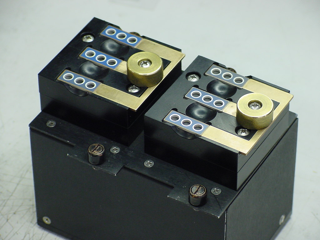
Versatile Module Adapters Optimize Production Efficiency
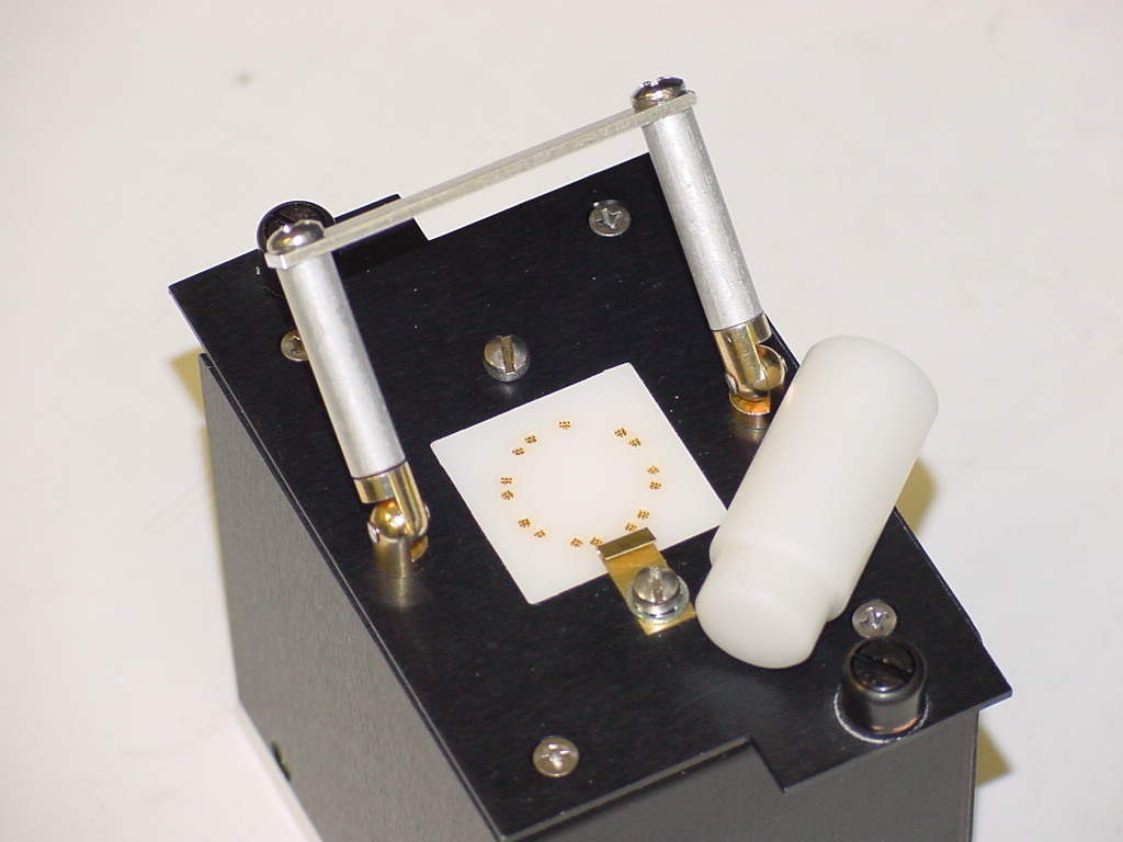
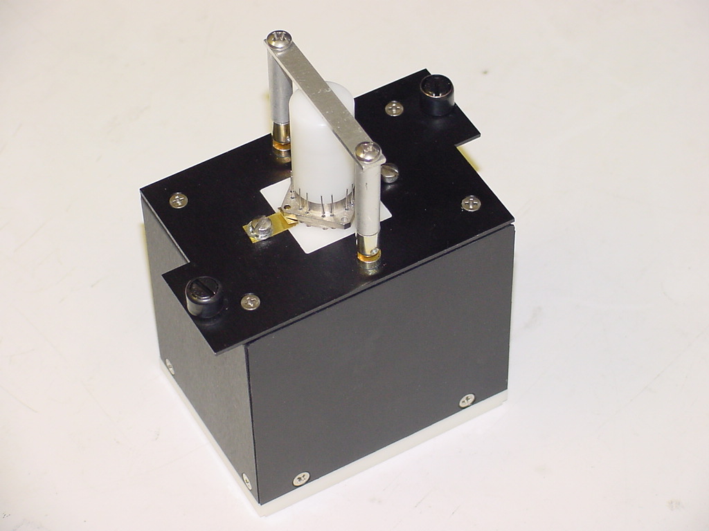
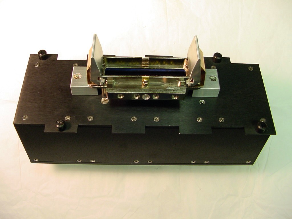
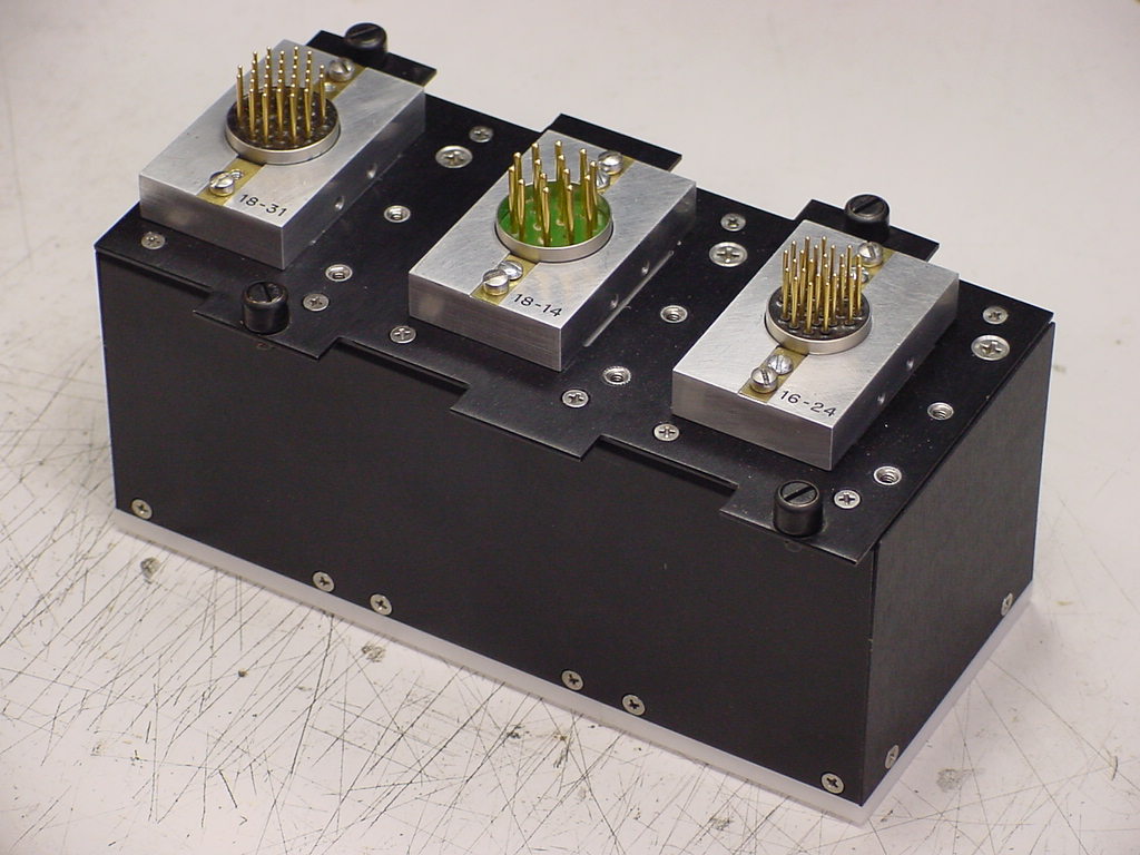
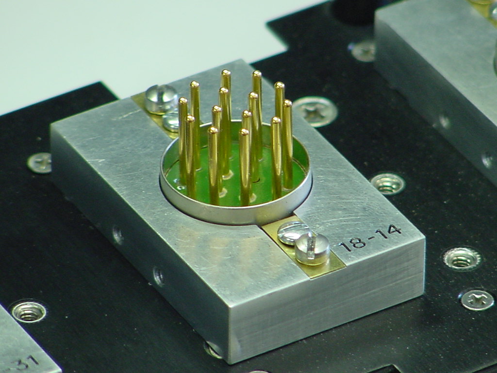
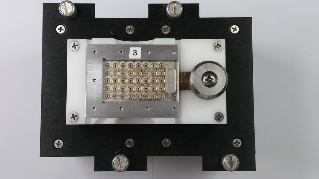
The older twist-cap design shown at right has been replaced by an improved cam-operated assembly whereby the array is moved against spring pins which scrub the interior of the hole in the capacitor array. This yields a positive 'scrub' connection and allows testing of the higher density planar arrays with little or no doughnut area available around the pin area. Twisting the knob slides the capacitor against pins. See picture below of 128-pin circular array module using new cam design. The 'twist cap' has been replaced by an improved design whereby a cam-actuated slider moves the capacitor array against the contacts for easier installation and cycling. See first photos of 128-pin array below.

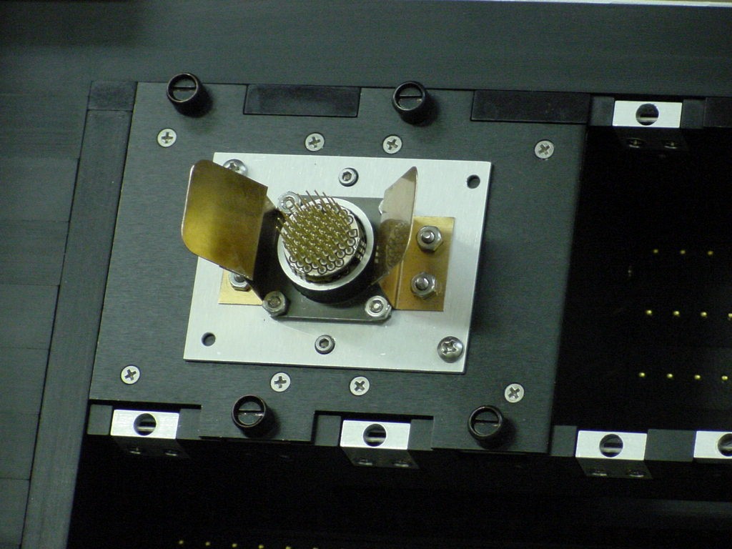
Gold Spring Contact Pins
Contact and register the parts.
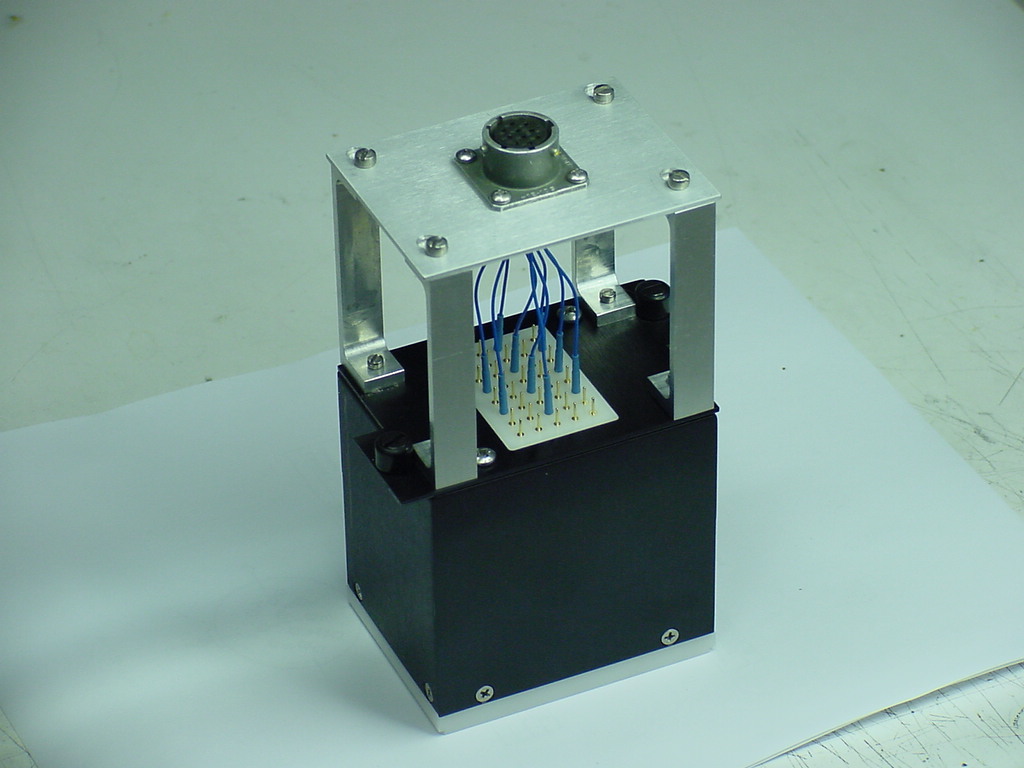
Final Product
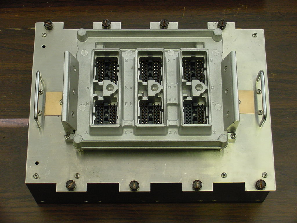
The device under test plugs into a replaceable mating receptacle for easy maintenance.
Interchangeable Test Adapters
Allows the testing of arrays or Subassemblies, or the finished product for versatility on a single module.
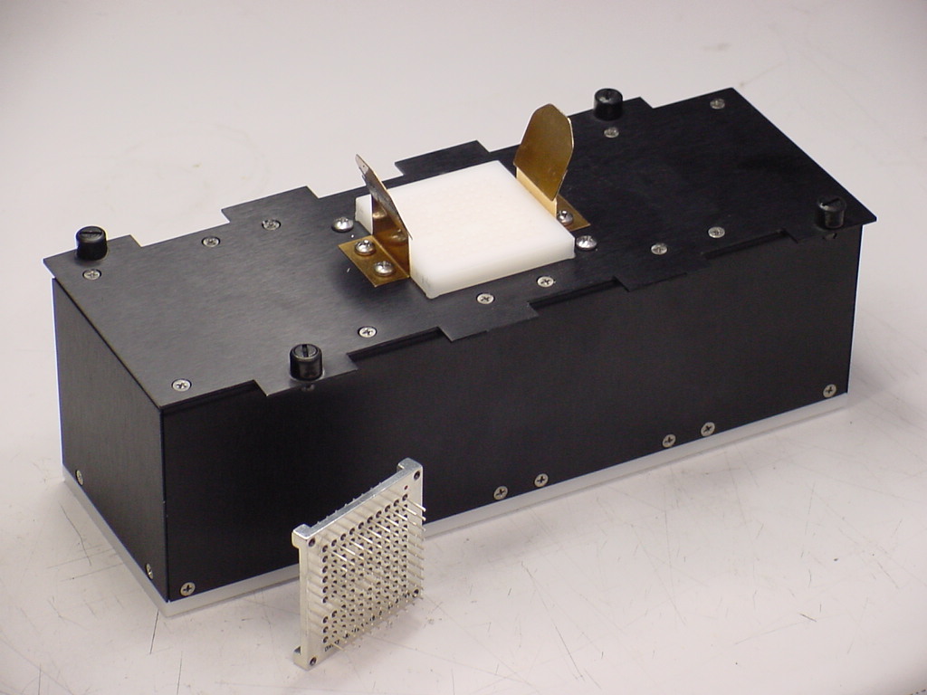
Test Modules/Fixtures:
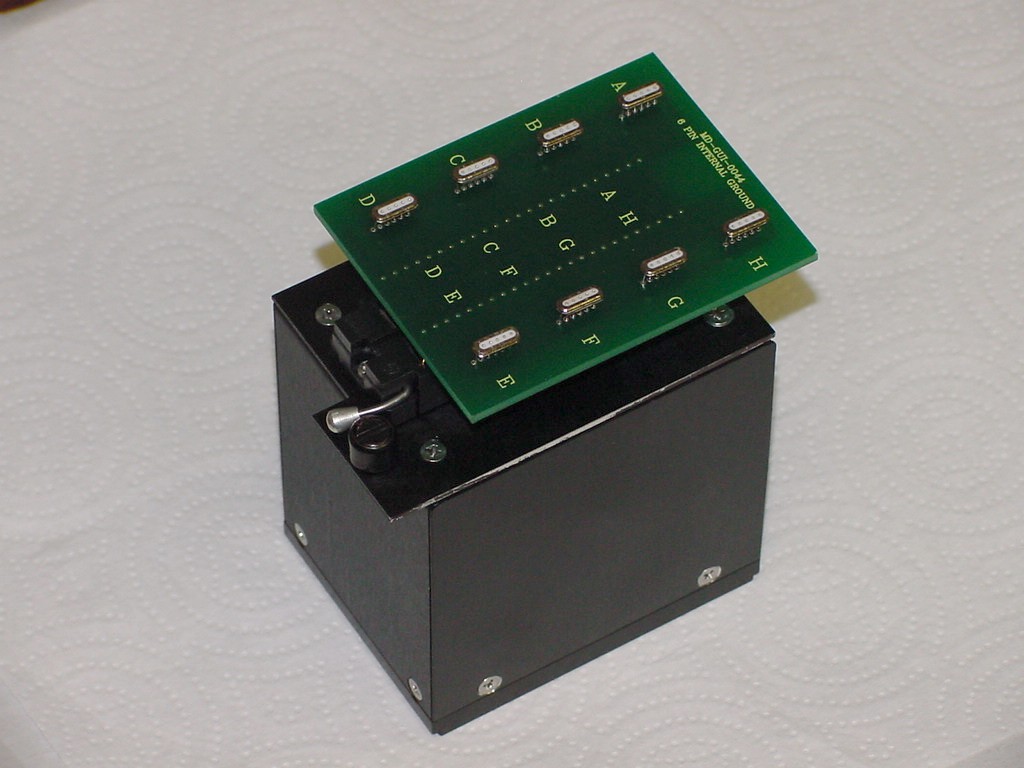
Modules seat and fasten into test bed using 1/4 turn DZUS fasters. Modules range in size from 40 pins shown in picture below to 160 pins and up to 320 pins in custom applications. Test bed accepts up to 8 forty-pin connector modules in same test cycle. Custom, universal module-adapter can be fabricated to utilize your company's existing fixtures/modules to this system.

Calibration Plug-In Module
Verifies system's electrical performance to a verified calibration standard.
Cover Safety Switch
Electrically disables tester with open cover to protect operator.
Test Options:
- Zener Diode: Reverse Breakdown Voltage (Uni-Polar, Symmetrical bi-polar and Non-Symmetrical bi-polar types) / MOV testing (750 VDC Limit) / TVS
- Dissipation Factor (DF) / Inductance
- Contact Resistance (0.004 Ohms Minimum; 4,000 Ohms maximum).
- Capacitance test conducted at working voltage; See "Memo to End Users" for more information on Capacitance Bias.
- Insertion loss plot vs DC bias voltage (optional).
- Ground ring isolation feature electrically separates pin(s) and shell for additional failure diagnostics.
Hardware Options:
- UPS (500 VA Uninterruptible Power Supply).
- 17" Touchscreen Monitor (SAW type).
- Barcode reader for entering/reading extended part/job numbers into parts menu.
- Temperature/Humidity/Barometric pressure instrument; data is transferred to printouts and recorded into reports in computer's database.
MEMO - TO END USERS AND MANUFACTURERS OF ELECTRONIC PRODUCTS AND SYSTEMS
As a manufacturer or end user of advanced electronic products and systems, you have ultimate responsibility for assuring signal integrity and protecting high energy circuits in your products. High-speed microprocessors, integrated circuit logic, memory and signal transmission products are more susceptible to EMI and RFI; and the consequences of loss of function and damage to sensitive equipment from defective connectors, improperly designed filters are much more severe, and in certain situations, mission or life-threatening.
Manual testing of connectors used in critical electronic components poses unnecessary risks because the connector's pins are not thoroughly tested one-pin-against-all-others-to-ground for leakage and shorts. The tedious labor-intensive method, prone to human error and omission and lacking in test verification / documentation, is still used by many connector manufacturers even now in 2010.
In the case of filter connectors, selecting the proper filter needed to attenuate disruptive frequencies is also critical to design of advanced electronic products and systems. Typical production test equipments are limited to testing capacitance at zero volts DC bias. The ConnectorTest systems have the ability to test capacitance at bias voltages from 0 - 750 VDC. Translating that result into filter performance, or insertion loss, for filters that are intended to be subjected to high voltage DC bias can be misleading, as capacitance of certain filter materials can change as much as 50% under DC bias voltage; this is a critical consideration for both the product designer and end user of filtered products.
Working with world class connector manufacturers, we at ConnectorTest International are eager to share our knowledge and experience with you. Please let us know how we can help assure you that connectors used in your products are tested to the highest quality standards.